Fluids & C°, in collaboration with the ESAin and PASS teams, is happy to present you the complete One-Stop-Shop solution for plant design and simulation.
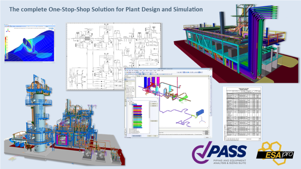
The design process
The complexity of an industrial plant makes it necessary to use computer systems that guarantee a simple, rapid design and that allow to speed up the construction or modification of the plant. The initial idea provided by the client must in fact be the subject of an in-depth study. It will analyze the most important aspects of the project: from the regulatory requirements to the different components to be used, up to the study of costs and construction times.
You must therefore analyze in detail and integrate with all the information necessary for the correct positioning of each element within the industrial plant, the idea provided by the customer. The first step is the realization of the P&ID (Piping and Instrumentation Diagram), the initial process scheme on which the entire design process is based.
Subsequently, you will carry out the study of the path of the pipes , through the use of a plant software that will guarantee a fast, accurate and precise three-dimensional modeling. The designers will then have a three-dimensional physical layout with which it will be possible to identify each element and extract the isometric sketches containing the list of materials, the list of welds and the cutting tables necessary for the next prefabrication phase.
The simulation tools
In the same time, we will show the associated simulation part of the main components and the piping of this three-dimensional modelling.
The first simulation tool provides diameter selection, heat and hydraulic analysis of steady state flow for real liquids, gases, and multiphase mixtures (including gas/liquid, oil/water, and gas/oil/water flow considering flashing and condensation), in piping systems of any complexity, including networks with loops. It also covers the most dangerous type of transitional flow related to liquid surge (water-hammer), and flow assurance calculations, including severe slugging, and gas hydrate formation prediction.
The second tool is so smart that you just need to use the piping from the 3D modeling software and push the button “run analysis”. The user should think about piping design, not about node numbering, model creation, etc. It provides comprehensive pipe stress, flexibility, stability, and fatigue strength analysis with related sizing calculations according to international and national codes and standards and will tell you if your model has any problems and show where exactly.
The last one provides pressure vessel strength and stability analysis for horizontal and vertical vessels, columns, storage tanks, as well as shell, tube, and air cooled heat exchangers under static and seismic loads in order to evaluate bearing strength in operation, test, and assembly states. It also provides finite element analysis of arbitrary vessel nozzles to estimate their stress, stiffness and allowable loads. The results can be automatically transferred to the piping stress analysis tool.
This webinar presents the ESApro tools for Plant Design and the associated PASS Suite tools for simulation.
Join us to learn how to save time and money.
Agenda
- Introduction (10 min)
- Presentation of the various tools, including demo
- ESApro P&ID, ESApro 3D Piping and ESApro Isometrics (25 min) by Francesco Pais
- PASS/Hydrosystem (25 min) by Sergey Lisin
- PASS/Start-prof (25 min) by Alex Matveev
- ESApro Cable Trays and ESApro Cable Routing (10 min) by Francesco Pais
- Q&A (15 min)
- Conclusion (5 min)
To know more, contact us.