Nozzle-FEM is available for Start-prof software users for free.
PASS/START-PROF and PASS/NOZZLE-FEM is free integration module that allows to use the finite element method analysis with shell elements to calculate the stress intensification factor (SIF) and flexibility k-factors, allowable loads on nozzles and analyze stresses in critical elements using FEA. Using this module allows to overcome the application limits of code and calculate the SIF, k, and allowable loads more accurately and less conservative which save the metal volume and reduce the piping cost.
PASS/NOZZLE-FEM software must be installed on the same machine with PASS/START-PROF. In this case PASS/NOZZLE-FEM will use license from PASS/START-PROF dongle. PASS/START-PROF will run and communicate with PASS/NOZZLE-FEM software automatically.
The SIF and k equations from ASME B31, ASME B31J, EN 13480, and other codes has the following limitation:
- D/t<100 of ASME B31, where D – pipe diameter, t – wall thickness
- The branch pipe axis should be normal to within 5 degree of the surface of the run pipe
- Not applicable for trunnions

Limitations of ASME B31 and ASME B31J
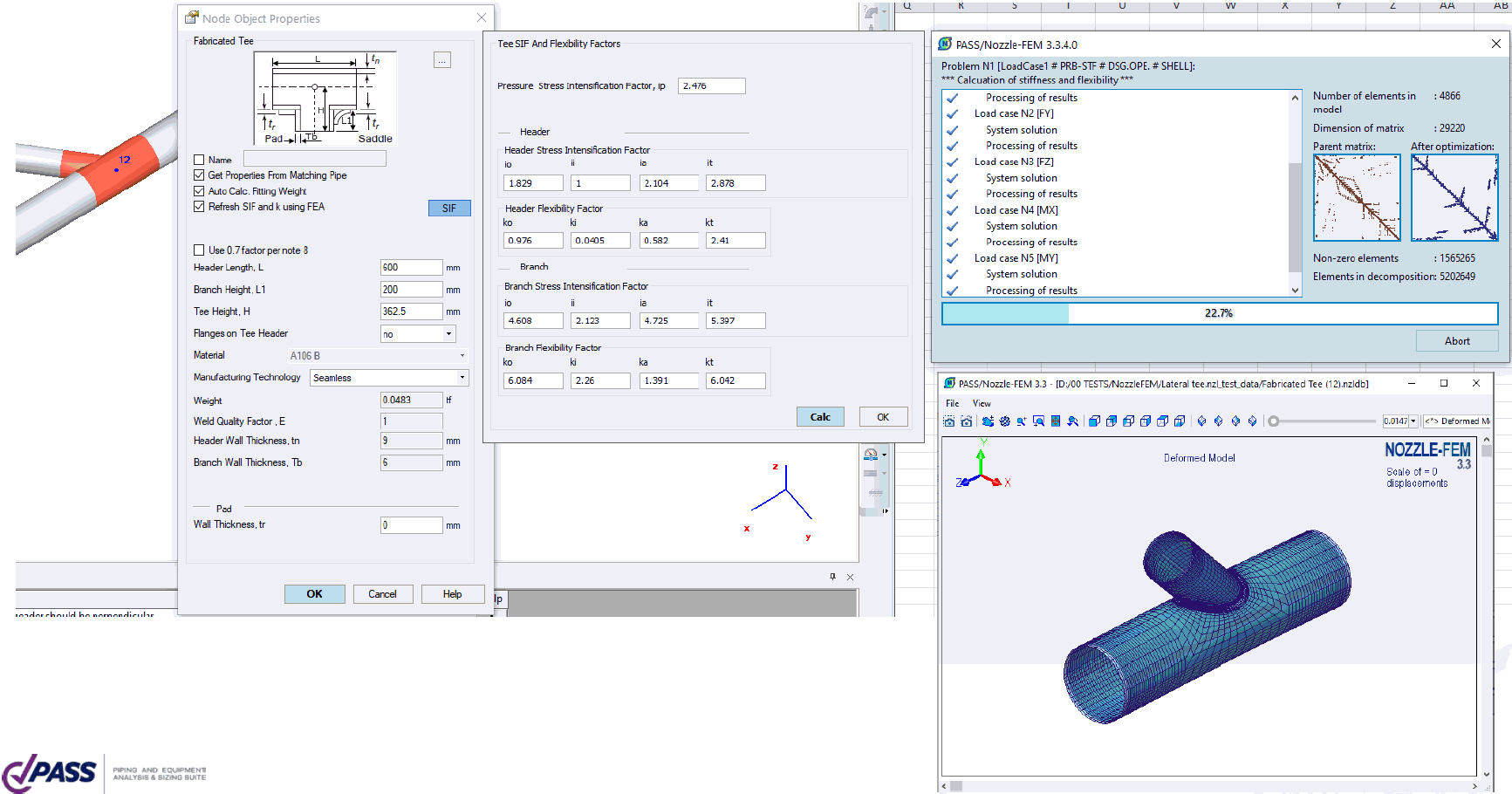
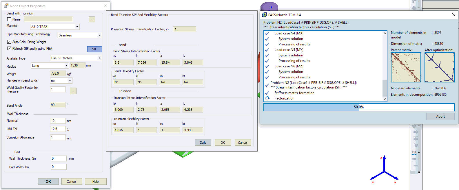
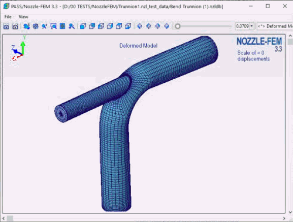
Using the PASS/START-PROF and PASS/NOZZLE-FEM integration allows to overcome that limits and also increase the accuracy of SIF and k values that satisfy the limits. You can calculate the SIF and k for non-standard configurations like lateral 45 degree tee, trunnions, bends and tees with D/t>100, etc.
The WRC 297 and WRC 537 documents for nozzle stiffness and stress calculation has the following limitations:
- WRC 297 limitation: d/D<0.5, 20<d/t<100, 20<D/T<2500, d/t>5, where d – nozzle diameter D – vessel diameter, t – nozzle wall thickness, T – vessel wall thickness
- WRC 537 limitation: d/D<0.33, (D-T)/T>50
WRC 297/537 are applicable only for
- Non-protruding nozzle normal to the vessel Surface
- Without reinforcement
- Only for cylindrical and spherical shell (may also be applied for ellipsoidal shell)
WRC 297/537 are not applicable for
- Tangential Nozzle
- Nozzle at not normal angle to vessel surface
- Nozzles protruding inside the vessel
- Trunnions
- With Reinforcement
- Conical shell, flat head, rectangular plate

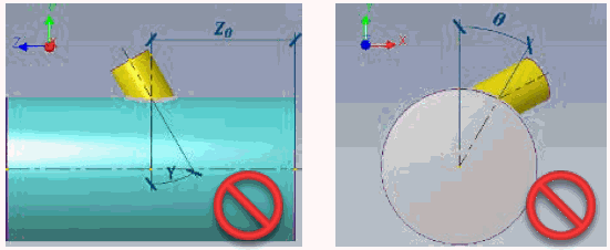
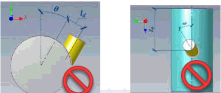
Using of PASS/START-PROF and PASS/NOZZLE-FEM integration allows to overcome all that limits including non-radial nozzles, protruding, with reinforcement, connected with rectangular plate, conical shell, flat head, storage tank nozzle, etc.
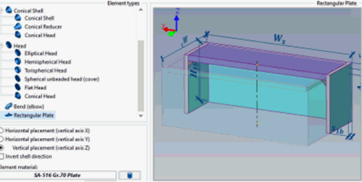
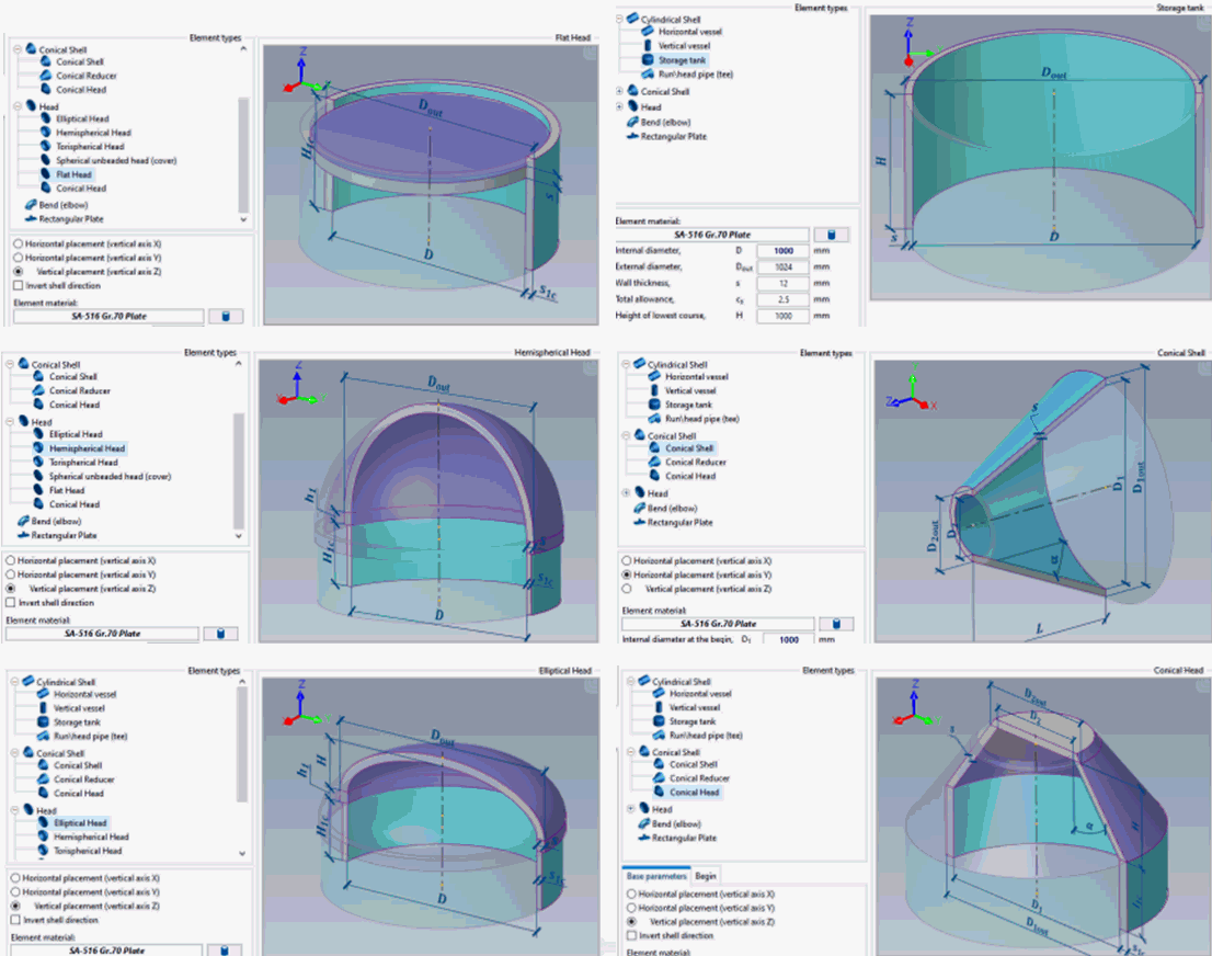
The list of functions available in the current version of PASS/START-PROF and PASS/NOZZLE-FEM integration module:
- SIF and k calculation for Elbow, Induction Bend, Custom Bend
- SIF and k calculation for Welding Tee, Fabricated Tee, Custom Tee
- SIF and k calculation for Trunnion on the Bend and Trunnion on the Pipe
- Allowable loads and flexibility calculation for Vessel Nozzle and Tank Nozzle
- Stress calculation and check according to ASME VIII Div. 1, ASME VIII Div. 2, EN 13445-3, JB 4732, GOST 34233.1, PNAE G-7-002-86 codes in Vessel Nozzle and Tank Nozzle
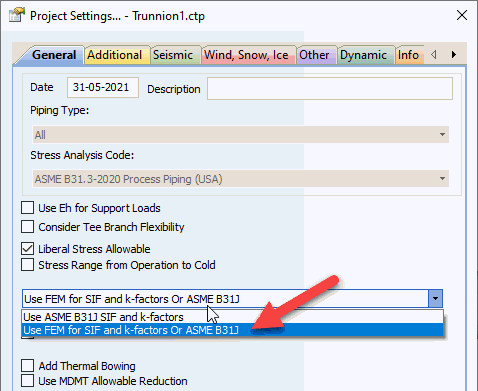
To run this integration interface just need to choose the “Use FEM for SIF and k-factors” in the Project Settings.
In dialog boxes of all elbow, tee, trunnion elements the button “SIF” will appear. And option “Refresh SIF and k using FEA“. Click the SIF button to see the SIF and k values that will be used for stress analysis. To refresh these values for a certain element, just click the Calc button. The finite element calculation of SIF and k values will be performed immediately for this element.
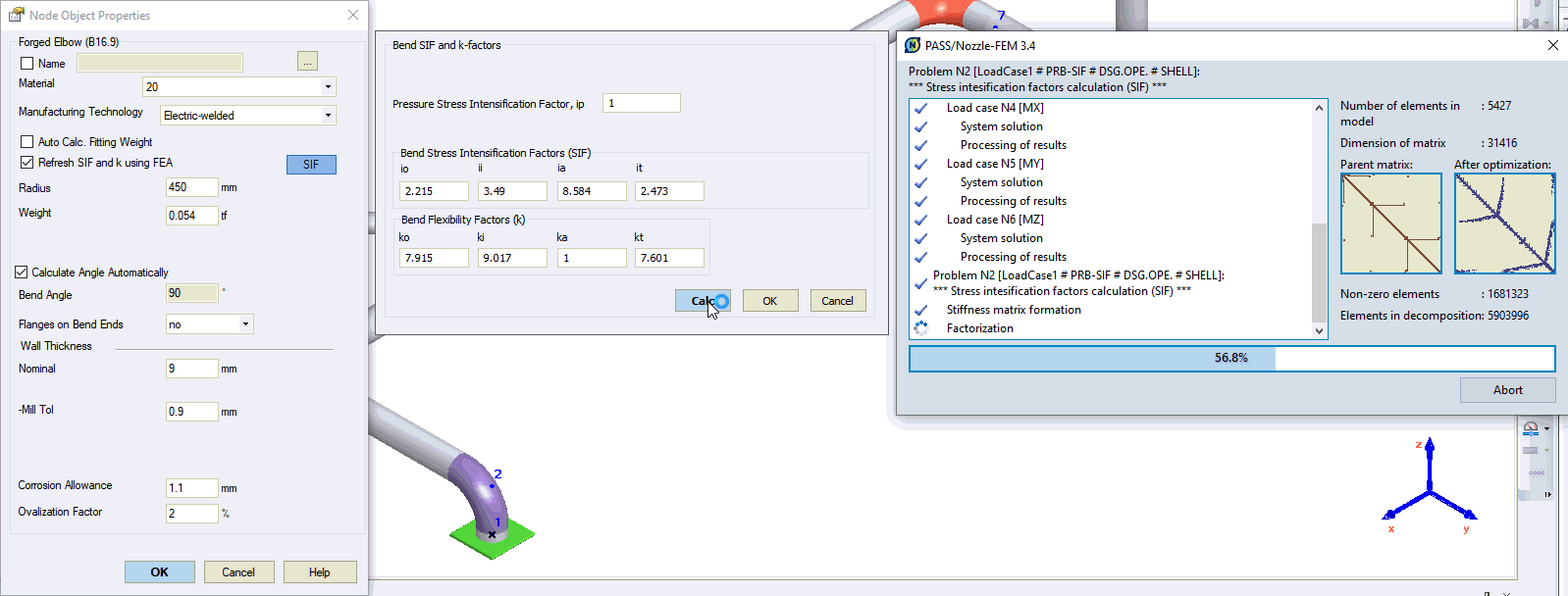
If “Refresh SIF and k using FEA” option is turned off, then you run piping analysis the SIF, k factors, and allowable nozzle loads will not be recalculated automatically. You can only refresh it manually by pressing the button “Calc” or enter the values manually.
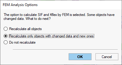
If “Refresh SIF and k using FEA” option is turned on, then you run piping analysis software will check the input data changes of the element and if difference is found, the show the following dialog box:
- Recalculate all objects – SIF, k and allowable load values will be recalculated for all objects
- Recalculate only objects with changed data and new ones – SIF, k and allowable load values will be recalculated only for objects with changed input data
- Do not recalculate – SIF, k and allowable load values will not be recalculated for all objects
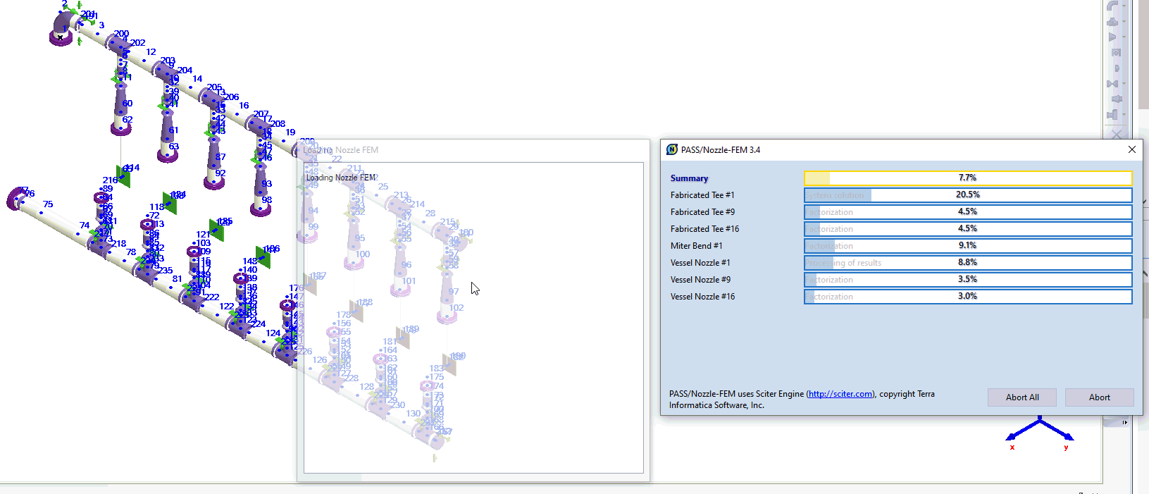
For optimization of calculation process, all identical objects will be automatically grouped to reduce amount of calculations, and after that simultaneous calculation of all bends, tees, nozzles, trunnions will be made using separate processes for each element with multi-core optimization. For example, the following model has 16 tees, one bend and 18 nozzles. START-PROF merged the identical elements and perform SIF and k analysis for 3 unique tees and one bend, and flexibility and allowable load calculation for 3 unique nozzles. After SIF and k calculation is finished, the ordinary stress analysis is done, but using the new SIF and k factor values.
For nozzle and tank nozzle elements you may select nozzle flexibility calculation “by FEM” and “allowable loads by FEM”.
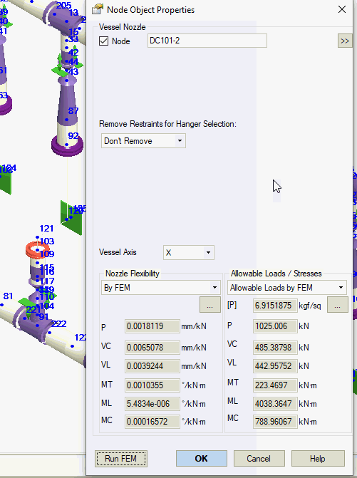
To change the nozzle properties click the “…” button. The user interface of PASS/NOZZLE-FEM software will be opened.
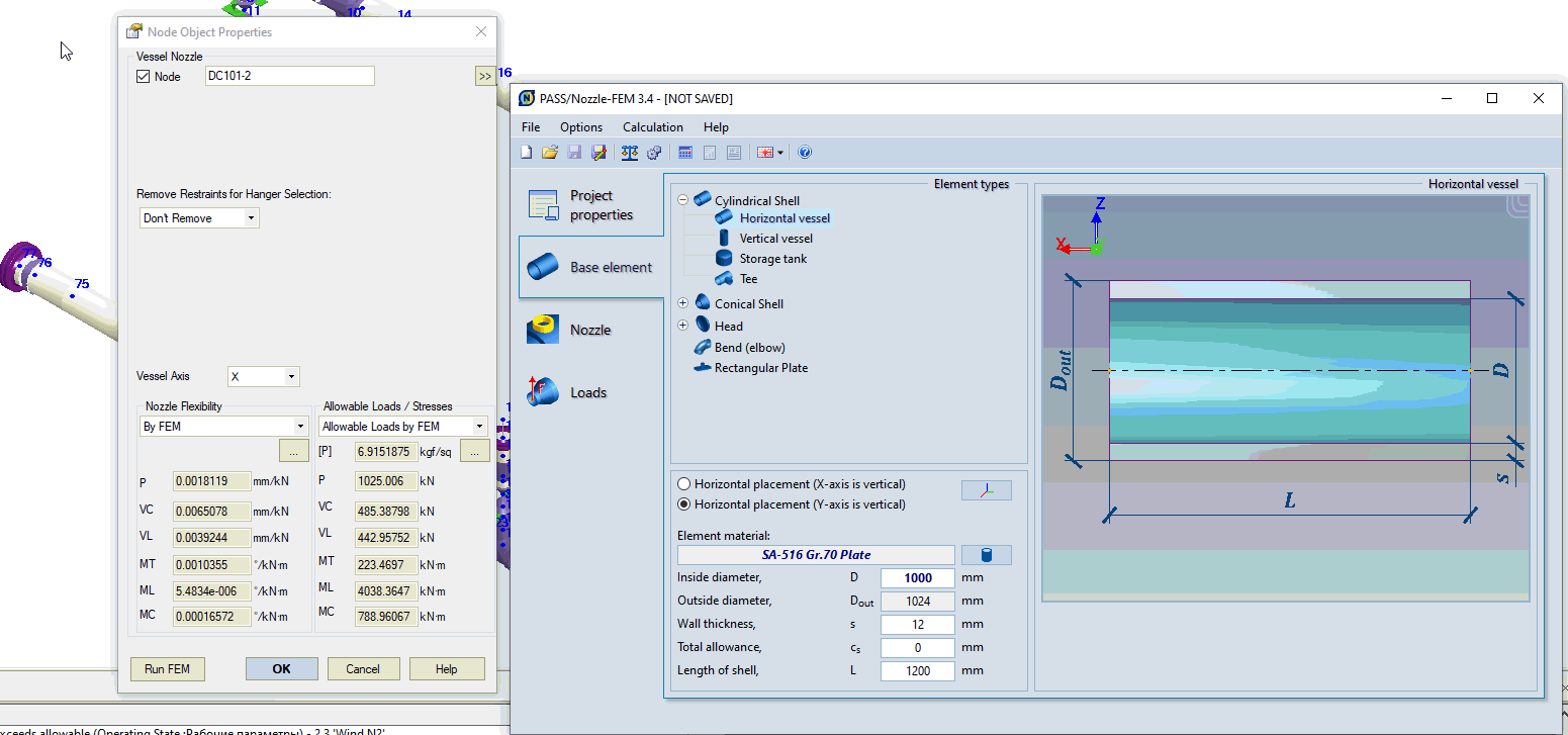
You may do any changes and then close PASS/NOZZLE-FEM. All changes will be returned back to PASS/START-PROF and saved into .ctp file. Also automatic calculation of the nozzle flexibilities and allowable loads will be performed. To run analysis from the nozzle dialog box, you may click “Run FEM” button.
If option “by FEM” is chosen, then START-PROF will run NOZZLE-FEM stress analysis again after piping analysis be finished. The stresses in the nozzle will be calculated and checked according to ASME VIII Div. 1, ASME VIII Div. 2, EN 13445-3, JB 4732, GOST 34233.1, PNAE G-7-002-86 codes. The result will be available in the table Loads on Nozzles and Equipment.
PASS/START-PROF will create the folder that is named the same as project file and put PASS/NOZZLE-FEM project files for each object into that folder for later review. Also the PASS/NOZZLE-FEM reports will be saved into the same folder in html formal.
To know more, contact us.
